How to Make a Use Case Diagram in Visio (UML for Business Analysts)
A use case diagram shows who uses a system and what they use it for. Learn the four UML use case shapes (actor, use case, system boundary, association) and draw a library system in Visio, step by step.
Step by step
Intro
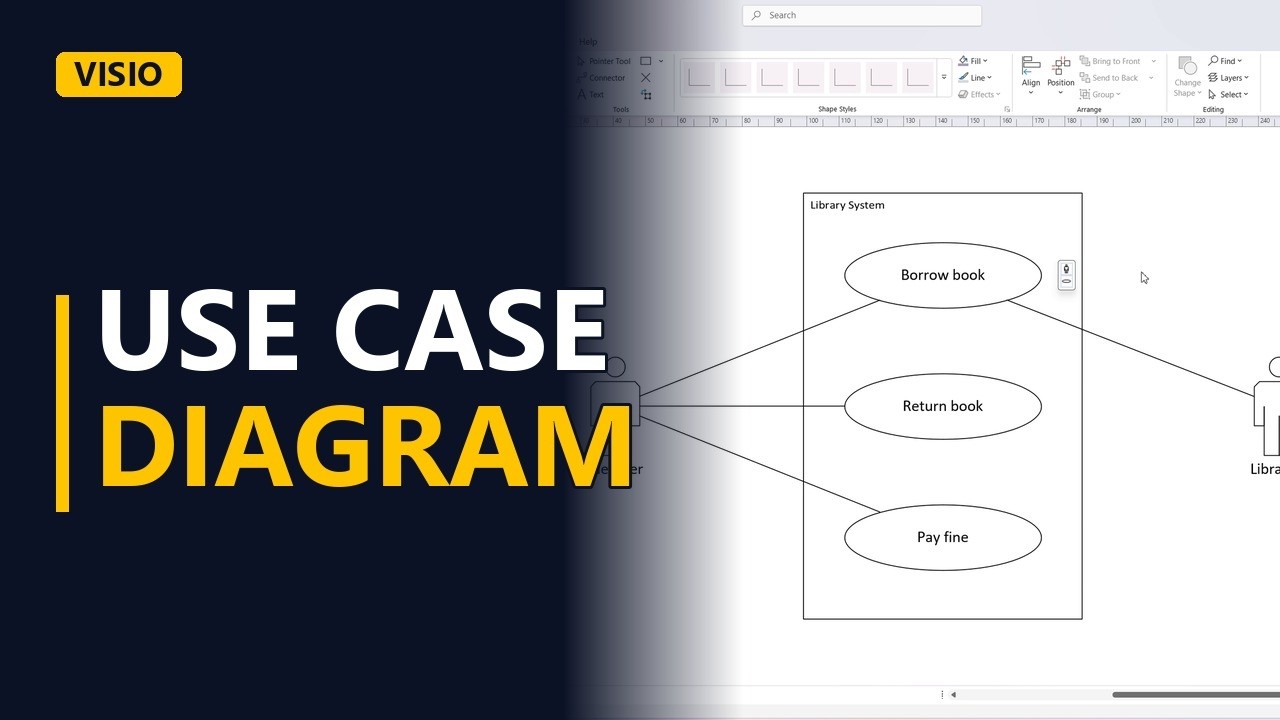
- Use case diagram. A use case diagram answers two questions. Who uses the system, and what do they use it for? Let's draw one in Visio for a library system.
- The UML Use Case stencil. I've opened the UML Use Case stencil. We only need four shapes from it.
System boundary
- System boundary. Start with the system boundary, the big box. Everything inside it is what the system does. Everything outside is not our system.
Actor
- Actor. Next, an actor, the stick figure. An actor is a role, not a person's name. Here, a library member.
Use cases
- Use case. Now the use cases, the ovals inside the boundary. Each one is a goal the actor wants to reach, written as a verb and a noun. Add a second goal, return book. And a third, pay a fine.
Associations
- Association. Connect the actor to each goal with an association, a plain line. No arrowheads. It just means this actor takes part. Member returns books. And members pay fines.
A second actor
- A second actor. Use cases often have more than one actor. The librarian checks out the book too, so add a librarian on the right. And connect the librarian to borrow book.
- Done. Click away to see the finished diagram.
3 use case rules
- 3 use case rules. Three rules. Actors are roles and sit outside the box. Use cases are goals, written as a verb and a noun. And keep it simple, the detail goes in the use case description, not the diagram. Subscribe for more Visio tips for business analysts.